Sunday 27 November 2011

WEEK FIFTEEN

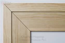
this week was spent fixing all the wall in the desired slots and screwed in place using a drill cordless drill and and posi drive then we went on to the architrave which is the  piece that goes around the edges of the windows they are all cut at 45 degrees angles and made to fit similar to the one featured
on the right


also the skirts were to be measured and cut to the right length before they were fixed how ever these were just square cuts like this one featured below these ran along the whole bottom of the sleep out and  along the tops aswell

WEEK FOURTEEN

we recieved help form the soxx team with our ceiling using the rondo steel system
like the on featured on the left notice the steel running along the inside benneath the rafters thus creating a steel  batten which the ceiling can be fixed to
after the rondo system has been applied to the ceiling in goes the insulation
which consists of R3.2
and then on top of the this will go the gib board which for the ceiling is 13mm standard
after the ceiling was in place we then used 10mm standard gib for the walls one side being standradr gid and the other being braceline
(braceline)

Monday 14 November 2011

WEEK THIRTEEN

on this week we had to complete the exterior battens on all the certain areas and also precise cut for the window flashing using chisels tho carve out a gap to make the batten sit flush we also spent time oin the lab in preparation for the presentation that is to be due in on the 16th


                                                  this man is installing exterior battens similar to the
                                                             one we used on the sleep out

Sunday 6 November 2011

WEEK TWELVE

on this week we did more of the exterior we used 20mm thick ply wood for the wall and put in our windows aswell we also installed the flashing which goes above all window fixings  made up of aluminium  alos we installed the ranch sliding door
simlilar to the on featured below
picture of flashing below
below is 20 mm ply wood

Sunday 30 October 2011

WEEK ELEVEN

this week was a short week we started on a tuesday and help the sox fix there rear exterior wall which was made up of colour steel iron we had to first put in the flashing on the bottom of rear wall on the exterior side then we had to measure the distance of  in which we had to fix the 100mm hex head screws makis ure the iron was at the right hieght we maintianed thios by using a 20mmm packer underneath every sheet of iron put on after al the sheets for the exterior rear wall ahad gone up we went on to fixing the iron for the roof before we did this we had measure the distance of every perlin once we had that we had to drill the roof with the required distances then a black sheet was layed down and fixed to the top of the rafters with cloud nails once the black sheet was pinned to the rafters we used the iron sheets and fixed it in place with a 50mm overhang on the front and drilled it to the rafters using the same 100mm  hex head screws that we used on the rear exterior wall

Thursday 20 October 2011

WEEK TEN

This was the last week for the term it was mainly spent on touching up the soft fit nogs and measuring out the wall cladding for the wall of the sleepout we had to cut the angle from the roof to match up with the wall cladding so it was able to fit and not have any over hang or gaps between the cladding  a big clean up was put into progress at the end of the week

WEEK NINE

on this day we started the day back on site completing the nogs for the soft fit area the soft fit area is located at the end of the rafters towards the front of the sleep out the nogs are put in place there to provide  a platform in which nails can be driven into these nails will fix the fibre lite to the nogs after it has been slide in to place on the fascia board . a fascia is a board which caps of the ends of the rafters and are gennerally put into place for the purpose housing the spouting system and to add a better touch to the fly rafter which is located directly underneath we also startted the cavity battens system which consisted of a breather sheet attached the purpose of the breather sheet is to ensure that the most minimal water gets through once the braether sheet has been applied it is must then be cut at certain areas such as the opennings for windows and sliding doors .

Sunday 25 September 2011

WEEK EIGHT

today time was spent on the rafters for the roof of our sleep out the hardest part was squaring it off and making sure that all the single rafters were square we also had  to stand the wall up and braced then  to the floor using our timber to level each wall so that the roof would fit on securely we used "G" clamps to hold the roof in place in the afternoon we headed into the computer lab and finished off the pricing sheets which were then handed in we also had an assessment on the computer which we had to complete the following day we started the morning in the class room learning about the different ways to lining the wall up using the dodger a dodger is a 20mm block fixed to the top plate on both ends then a string line will be ran from one block to the other forming a straight line then we used a identical 20mm block to measure the distance between the top plate the 20mm is for the thickness of the cavity batten to be fixed to the  and the string line the block must fit with out disturbing the line at any time all the way along the top plate we to do this we used 2x4 timbers cut to size as braces fixed to the stud as close to the top plate and use this brace to line it up then used this same method to line up the front wall thus bringing our four constructed wall together then fixed packers along the side of the front wall and used them to hold the front wall to the side walls then fixed the rafters to the top plate and aligned them so they were all parallel once the roof was in place the fly rafter had to be attached to the top plates then we made out sprockets these make up the remainder of the roof they run from the last rafters on both ends to make up for the over hang  nogs were also put in place to make a corner so the wall cladding can be fixed on to something after noggins were in place we then had to nail our fly rafter to the end of the rafter and along the sides on the ends of the sprockets creating the safit of the building
(dodger is pictured above)
(above is a picture of a roof construction the fly rafter is labbeled)
(the picture above is a sproket)

Sunday 18 September 2011

WEEK SEVEN

Today was spent in the workshop finishing our saw horses so that we could use them to help elevate us when the time comes for us to be needed in a high place to fix the certain areas of our constructed building before we started any cutting we had to mark out the areas in which we were going to cut this came from a plan where we had to measure in from the edge of our plank a certain distance and mark it then we had to established the angle for the legs to be fixated on to we did this by measuring 20mm in and 60mm up to create the angle that was required for the legs to sit in a stable manner  (similar to the one below)
a bevel was used to maintain the angle that we had found from there we had to skillfully use our Saw to cut the desired angle for our legs to be fixed in to and using a chisel to chip away at the excess that remained  when that was all done our legs had to be in and shaped to fit flush with the top of the horse after the legs were fitted we then had to create a brace to add more strength and support to the horse and the task it will be fulfilling in this week we also had put together adrawing board for ourselves which consisted of three finely planed 15x145 planks which we glued together and kept flush on both the surface and the edges .to make sure that three planks did not seperate we used clamps to ensure that they remaineed in the position that we set thm to be at ,removed any excess glue and waited for them to dry after they had dried we used they belt sander to remove any glue that had dried on the surface and to make it completley smoother and even all the way through the board we then used a 15x 45 plank and measured 10 mm down on oppsite side to create an angle which we cut using the hand saw and made to triangular legs for the base of the drawing board we set them side by side and using the planner evened out as much as we could before fixing them to the bottom of our drawing boards using square head screws 
     (on your right is drawing board)

Saturday 10 September 2011

STANDARDS,CODES,REGULATION

BUILDING ACT

the building  as of 1992 changed from what you must do to what you must achieve
the objective was to provide safeguards for people from injury or illness, safeguard those particularly with a disability from the loss of required access tools,also made to protect other property from being damaged and the efficiency use of energy.The building act does not have any control on the structure, design or colour factors of a non essential building or the economical interests for the building.

WHAT IS A BUILDING


A building is defined as any fixed or non fixated construction deemed to be there for a night or eternity. Regardless weather the building  is used for people, animals, machinery and/or sleep outs such as the one we are constructing , this also applies to the electrical and mechanical systems attached to the construction to form part of it.They must have the necessary compliance with the building

NEW ZEALAND BUILDING CODE

A schedule for building regulation authorised by the building act.it contains legal performance based
preparation for meeting the purpose of the act, the building code also includes documents such as

ACCEPTABLE SOLUTIONS for those who prefer specific guidance. there are a number of acceptable solutions (they do no cover all aspect of constructions) which if used ensure compliance with the NZBC performance requirements.there is no obligation to adopt a particular solution

VERIFICATION METHODS
provide the means to verifying or proving compliance with the performance requirements f the NZBC
compliance with                            
New Zealand or over seas standards may also be used as a means of verifying performance

ALTERNATIVE SOLUTION
Any other construction method or element not covered by an acceptable solution whose compliance with NZBC has been  demonstrated to the building consent authority or Territorial authority either by test calculation history of use or other supporting evidence

NEW ZEALAND STANDARDS

standards are relevant to the design and construction of timber framed buildings
consist of three main types

ACCEPTABLE SOLUTIONS
which are standard of the type of wood and wood based products
the durability of the framing and the timber components that go with the frame
all the concrete masonry that don't require a design
and all the stucco plastering

another standard is that of which you must verify the material or product  so that it  will  meet the performance of the building code

the last building code is the set standards for the manufacture of or a certain material or component used

WHAT IS ??

JACK STUD
a jack stud is any stud that is smaller then the original stud on the selected  framing refer to the diagram below week six

TOP PLATE
is a horizontal timber member of the framing found at the top of the frame they are in junction with the studs

600 CENTRES
refers to the distance in which your studs must sit,so when your stud is introduced to the top plate the middle if the stud must be at 600mm.To get this 600mm you must first minus half the amount of the width of the wood and in this case we a re using 45x90mm so half of 45mm will be 22.5mm,you then take this 22.5mm  and minus it from the 600 centres you started with giving you an answer of 577.5mm this will be your first measurement out form the edge and then from there on you simply measure 600mm till the timber is no longer


WEEK SIX

Today we cut and mesured the sheets for the floor and fixed them to the floor joists underneath we first had to measure distance from on our sheets to line up then nailed the sheets in and created the floor. From this point we fixed together our bottom plate for the rear wall made up of one treated 90x45, after this was established the bottom plate for the side wall was measured out and cut.Along with the top plate which will contact the front top plate at a lower height by the roof rafters to put the roof on an angle. we measured the distance from top plate to bottom plate for to determine the length of our studs that will go on the wall.Today we finished constructing together the the wall framing for both sides., with the required inserts for the windows  started the rear wall measured our studs for the rear wall and also put in our nogs and packers nogs are to provide a the studs with more stability for the framing of the wall, packers are designed for one purpose and that is to provide a binding point for the rear wall and the desired wall in this case it will be the side walls

Sunday 4 September 2011

WHAT IS A LINTEL

 1= top plate                   
 2 = jack stud  above lintel         
 3 = LINTEL                                 
 4 = interior wall                                                                                               
 5 = jack stud                           
 6 = top plate for door     
 7 = under stud for window
  8 = stud 
9 = jack stud under the sill
10 = window sill
11 = nogs
12 = bottom plate

LINTEL
In this diagram the lintel is marked under the number 3 the purpose of the lintel is to provide added strength and support for the window that will be put in place there are many types of lintels however the most common one that the builder will use is a timber lintel (shown in the diagram above)

U/S(UNDER STUD)
the u/s is shown here in the diagram marked with the number 7 the purpose of the u/s is also to provide strength for the lintel above the under stud the only place  you will locate an u/s is underneath a lintel

WEEK FIVE

this week we started by perfecting our Pythagoras method both 3,4,5 and the square root method .We then applied this to our sleep out plan which we had already marked and set profiles for.Down went the sole plate for the rear and front of the sleep out followed by the jack studs that were used to level the floor of the sleep out, above the jack studs went bearers on both front and rear of the sleep out,boundary joists were measured and cut for the sides and also the front rear. we then measure the distance in between and cut out joist to fit in between the boundary joist along the width of the sleep out  applied "Z" nails to secure the joist in to place

PROFILE SET OUT FOR SLEEPOUT

DESCRIBE THE PROFILE SET OUT
(refering to sleep out)
profile set out can only begin once the building line has been established.We did this by taking a point from the boundary line and measuring in to a certain point, were  we thought would be fitting for the dimensions of the sleep out which are det out at 5.1x2.8  Once this was established  we measured out the width and the length of the building  out to the most furtherst point and also marked it. Once the building line was marked we measured 700mm out from that and set up our porfiles.These profile had to be a little longer to allow a nail to set on top of the batterboard giving a place for the stringline to be hooked on to. after setting up the profiles we then measured the distance of both sleep outs to be constructed along with the distance between them this gave us the measurement for  the edge of the building which we made noticable by running a string line along at every point from batter board to batter board to give us an indication of where these point will br and also to make squaring our builing off easier

Sunday 28 August 2011

TERMINOLOGY FOR SLEEP OUT PLAN


(ACCORDING TO BRACING PLAN ABOVE)

[M----- ]= left hand side rigid wall       
[N----- ]= right hand side rigid wall
[A----- ]= rear rigid wall
[B-----] = front rigid wall

[N1] = The amount of Gib required and the wall it will go on [BL1] = the type of Gib board used [0.4] = the measurement in mm
[N2] =  the amount of Gib required and the wall it will go on [BL1] = the type pf Gib board used [0.4] = the measurement in mm
SO IN CONCLUSION : There will be two sheets of BL1 Gib board at 0.4mm each situated on the inside of the right rigid wall

[B1] =The amount of Gib required and the wall it will go on [BL1] = the type of Gib board used
[1.0] =  the measurement in mm
SO IN CONCLUSION : there will be one sheet of BL1 Gib board at 1.0mm  situated on the  inside of front rigid wall

[M1] = The amount of Gib required and the wall it will go on [GS1] = the type of Gib board used
[1.4] = the measurement in mm
SON IN CONCLUSION ;there will be on sheet of GS1 Gib board at 1.4mm situated on the inside of left rigid wall

[A1] = The amount of Gib required and the wall it will go on [GS1] = the type of Gib board used
[1.8] = the measurement in mm

[W1] = Tells us there is one window  which on this plan is a sliding ranch door situated on the front rigid wall the lintel fixings are also given for this window it will be 2/190x45mm

[W2] =   tells us there is another window situated on the right rigid wall with lintels fixings 2/140x45mm

[W3] = tells us that there is a window situated on the left rigid wall with lintel fixings 2/90x45mm

[B] = top plate fixing for the walls


(ACCORDING TO THE ROOF PLAN ABOVE)

[R1] = roof rafters these will made up by 140x45 sized timber set at 600 centers apart and this plan also tells us that the rafters will be on a 6degree angle


(REFERRING TO THE FLOOR PLAN ABOVE)


[F1]  = lets us know that what your looking at is the sub floor frame

[A] = the black blocks that are marked [A] signify that those piles will need to be anchor piles and the remaining will be normal piles

Friday 26 August 2011

WEEK FOUR

This week began with us being in the class and we were given a class group team task of creating a poster showing the different requirement needed for a site sectioning such as the SITE SET OUT which is given to us BOUNDARY PEG, BOUNDARY LINES, BUILDING LINES, TIMBER PROFILES,  and what we didn't really touch on was the METHOD PYTHAGORAS  also we had the opportunity to draw cross sections based on the sub floor framing we got given the chance to update our blogs in the computer room for the remainder of the afternoon on the follow day we were given the opportunity to complete our  joint exercise  and were taken out in to the site to get a chance to use the DUMPY,AUTO LEVEL, LASER LEVEL a dumpy is an optical tool used by either SURVEYOR to measure the horizontal check points are the same or a BUILDER to transfer ,set or measure the horizontal levels of the landscape the DUMPY  is set on the TRIPOD and then it must be set according to the spirit level situated on the side of the optical lens.It has 3 ADJUSTING  LEVELS  a  ZOOM  and a FOCUS knob under neath the lens is a screw on  fastening used for a lose screw used to brace the lens on to the TRIPOD  we were also told about the FALL it is the measurement up from the level horizontal plane in this case our fall is 120mm from 150mm which in this case is going to be ground level we were also shown the PYTHAGORAS it is the measurement of the hypotenuse which is the distance located opposite the right angle of a right angle triangle to find this measurement we must find out the two measurement of the remaining walls of our triangle add them together using the power of two method which is to multiply a number into itself using no more and no less  then its equal amount equal amount to receive a a number that is to the power of 2 or squared (i.e 444x444= 197'136=A)(i.e777x777=603'729=B) after you have gotten both sides of the triangle using this method you must add those numbers together to get an answer which you must square root that final answer to get the exact measurement (i.e 197'139=A ,603,729=B)(i.e A+B=HYPOTENUSE)(i.e then you square of the HYPOTENUSE) and then you get your answer. The following day was spent in the work shop finishing our joint exercises once we had completed that we then went on to creating our saw horses. we were shown the thickneser machine which planes down wood too any measurement  by setting the thick electronically. once set you feed your plank through the instructed side. The other machine that was shown to us was the buzzer. It planes(refines) the desired side of the timber you must be very careful not to run your fingers over the blade . In the afternoon Sue Bartlet came in and told us about communication,and the barriers in which can get in the way.Such as emotional problems that can be occurring which would cause a break down in communication.Another one could be noise that could distract the the student there for failing to hear a message then been asked to share the mess but the noise distracted the student  could cause problems and  therefore failing to communicate properly .Kerrie Brown also gave us a reminder and continuation on safety in the work place and the importance of there role in the institute

WHAT IS A SITE SET OUT

A site set out consists of 

BOUNDARY LINE
a boundary line is a line which defines the most furthest point in which your construction can reach.At no time can the construction pass this boundary line.because you will have to move the whole building.
it will be time consuming and cost alot  to do so


BOUNDARY PEGS
Boundary pegs are short whites peg like timbers with a copper nail on top. Used  not only set out the boundary line it helps on houses that are on an odd angle,using the peg as a marker it does this by using set out lines. They are measurements set out from the peg to determine the position of the building


BUILDING LINE
The building line is the line in which you have proposed to have your building to be erected.


PROFILES
Is a timber construction held together by a batter board.It is used to to give a guideline to where the proposed building line is going to be.It can be no closer than 900mm to the building line to allow for access around the building

Monday 15 August 2011

WEEK THREE

During this week  we started the sketch of our floor plan trying our best to use the scale rule to effect in our drawings we were able to label and name all the sub floor parts such as PILES, FLOOR BEARING, FLOOR JOISTS, and with these part we were told to measure the needed quantity and set a price for each of the certain types of timber required such as 

4xBEARINGS(H3.2 treatment)

2 BEARINGS @5.700m
2 BEARINGS @4.320m
 
7xBARRIER JOISTS (H1.2 treatment)
2 REAR JOISTS @5.700m
4 SIDE JOISTS @3.100m
1 FRONT JOIST @4.320m

10xJOISTS @2.065m(H1.2 treatment)

10xNOGS @.387m


our tools were also distributed out to us and all our stationary  which included

TOOLS:
1xHAMMER
1xRULER
1xMEASURING TAPE
1xCOMBINATION SQUARE
1xHANDSAW
1x19mm CHISEL
1x32mmCHISEL
1xBUILDERS PENCIL

STATIONARY:
1xRED PEN
1xBLUE PEN
1xBLACK PEN
1x2H PENCIL
1x EL-531WH CALCULATOR
1xSKETCH PAD
1xFOLDER
1xRULER

and to end off week three we spent the whole day in the work shop perfecting our joint exercises which consisted of the CORNER HALVING, STOPPED TEE HALVING, SINGLE DOVE TAIL HALVING AND THE DOVE TAIL HALVING how ever we did not get to attempt the dove tail halving due to the time we also learnt to cut the angle of the single dove tail halving which i thought would prove to be a challenge  but a steady hand and a-lot of concentration proved the job to become a simple task  

Sunday 14 August 2011

WEEK TWO

This week we started on our joint exercises and it was the first day in the workshop.We were introduced to specific hand tools that were required for this exercise such as a handsaw,  combination square, hammer, chisels and most importantly the different classes of wood we are required to use and the many terms that they are refered to such as the 10,8,6,4, and 3x2 or otherwise known as the 70x45. In the afternoon the library was on the agenda, as Ingrid showed us all the different services that were available to us as students of the institute.We were also given the opportunity to use the very intricate dewy decimal system that had been put in to place by staff. to gather certain books that would prove very helpful in our journey.Ingrid was kind enough to show us more helpful resources in from of Internet by using the EMIT network, there we were able to  follow different links to get to what we wanted to find such as the MONTIE SAFETY PROGRAMME which would prove helpful as the programme progressed.the following day we continued to practise on our joinery pieces we were shown the right way to use our chisels so that the edges of our pieces would not be blown out we got the angles required for our dove tailing cut outs and later on that afternoon we were back int to the computer room where we shown how to post in to our blog and also how the emit  programme  would prove an advantage to our studies  and before the day ended we entered the lab for the first time and there i created my own blog on the blogger website on the Wednesday we were shown the cross section of the sleep out we were building in time to come.And the make up of  the sub floor  these include  the joist,bearing,piles and other components  we continued with our joinery pieces we had the chance to use the power tools for such as the drop saw and the wall  grinder above all that we we given the instructions on how to use the power tools correctly  without harming ourselves as well as our class mates  

Thursday 11 August 2011

SUBFLOOR TIMBER MEMBERS AND SIZES


MEMBER:joist
SIZE:140x45
TREATMENT:H1.2


  MEMBER:bearer
SIZE:145x40
TREATMENT:H3.2


(no image for piles)

MEMBER:piles
SIZE:125x125
TREATMENT:H5

WHAT IS A POWHIRI

A powhiri is a traditional Maori welcoming ceremony that would usually involve a
korero(talk)
kanikani(dance)
waiata(song)
and a hongi which is the traditional Maori greeting using the nose instead of the common hand shake the powhiri can serve two purposes such as welcoming manuhiri(visitors) onto the marae(sacred building) or to dedicate the actual building powhiris can be perfromed for tourist groups as part of a special event

below is a picture of a hongi


Tuesday 9 August 2011

HEALTH AND SAFETY

health and safety is an important task to undergo when dealing with the construction industry.
It could mean the difference between life and death for you and the workers around you so it is the job of the department of labour to make sure that your work place is a safe environment to be able to work in. this means that anything you use to help you complete your job is safe to operate and also is not going to harm anyone. The D.O.L also visit to see if the way you operate any equipment is unsafe for you and the people around you so my opinion is it is basic common sense if you ask me

WHAT HAVE I LEARNT?

So far i have learnt  about the safe use of tools.And also the reason why they should be used in a safe manner, for instance like making sure the guard on the drop saw is working properly otherwise it could get stuck on the object your cutting and the drop saw could jump and cause whoever is operating the  drop saw serious injury maybe even death. also along with the safety of other electrical tools used in the trade.

Monday 8 August 2011

WEEK ONE

on week one i started class and we were taken through a health and safety talk regarding our safety in and around the campus we also were introduced to the student services and took a tour around both north and south campus we had the security come in and talk to us regarding the services they provide and showed us the location on where they could be found around campus a powhiri was also on the agenda on week one giving us an opportunity to meet and greet other students whom were in-rolled on the second semester along with us above all that we had a basic run down on the different power tools we would be using and the safety precautions used when dealing with these different tools we began a rough we learnt the different attempt on drawing the sleep outs we are going make and also received and engraved our ear muffs we learnt why scales were used on drawings and why we didn't need a consent from the council for the sleep out and after all that we were set homework to explain what the treatment H3.1 meant.